--部分模塊代碼如下:完整代碼及文檔說(shuō)明附頁(yè)下載,工程用quratus 13.1以上打開(kāi)
2.設(shè)計(jì)內(nèi)容
3. 系統(tǒng)的主要功能及使用方法
4. 數(shù)字電子鐘的VHDL設(shè)計(jì)
4.1設(shè)計(jì)思想
4.2設(shè)計(jì)電路圖
4.3模塊說(shuō)明
4.3.1 分頻器
4.3.2功能選擇器
4.3.3一輸入二輸出器
4.3.4計(jì)數(shù)器1至計(jì)數(shù)器6
4.3.5計(jì)數(shù)器(1-3)的校正器、計(jì)數(shù)器(4-6)的校正器
4.3.6防止異步清零器、異步清零器、數(shù)碼管選擇器、led燈選擇器、數(shù)碼管顯示時(shí)間器
4.3.7頂層文件
4.4硬件配置調(diào)試
4.4.1硬件要求
4.4.2引腳綁定
4.2.3現(xiàn)象說(shuō)明
5. 實(shí)驗(yàn)總結(jié)
5.1錯(cuò)誤和解決方法
時(shí)鐘是我們?nèi)粘I钪斜貍涞纳钣闷分弧6鴶?shù)字時(shí)鐘的出現(xiàn)更是給人們的生產(chǎn)生活帶來(lái)了極大的便利。鐘表的數(shù)字化給人們生產(chǎn)生活帶來(lái)了極大的方便而且大大地?cái)U(kuò)展了鐘表原先的報(bào)時(shí)功能。諸如定時(shí)自動(dòng)報(bào)警、按時(shí)自動(dòng)打鈴、時(shí)間程序自動(dòng)控制、定時(shí)廣播、定時(shí)啟閉電路、定時(shí)開(kāi)關(guān)烘箱、通斷動(dòng)力設(shè)備,甚至各種定時(shí)電氣的自動(dòng)啟用等,所有這些,都是以鐘表數(shù)字化為基礎(chǔ)的。因此,研究數(shù)字鐘及擴(kuò)大其應(yīng)用,有著非常現(xiàn)實(shí)的意義。 本次設(shè)計(jì)的目的就是在掌握EDA實(shí)驗(yàn)開(kāi)發(fā)系統(tǒng)的初步使用基礎(chǔ)上,學(xué)習(xí)較復(fù)雜數(shù)字電路系統(tǒng)的設(shè)計(jì)。EDA技術(shù)為數(shù)字類產(chǎn)品提供了一個(gè)非常簡(jiǎn)便實(shí)用的開(kāi)發(fā)平臺(tái)。隨著EDA技術(shù)的快速發(fā)展,數(shù)字時(shí)鐘的應(yīng)用越來(lái)越廣泛,并且它在功能外觀方面也有了很大的改善和提高。本文就是基于EDA技術(shù)的基礎(chǔ)知識(shí),利用Quartus2軟件再現(xiàn)一個(gè)具有傳統(tǒng)時(shí)鐘功能的數(shù)字時(shí)鐘。 2.設(shè)計(jì)內(nèi)容設(shè)計(jì)內(nèi)容: 設(shè)計(jì)一個(gè)電子鐘,要求可以顯示時(shí)、分、秒,用戶可以設(shè)置時(shí)間 設(shè)計(jì)具體包含的模塊內(nèi)容如下: 要求: (1)根據(jù)系統(tǒng)設(shè)計(jì)要求,采用自頂向下的方法,劃分系統(tǒng)主要模塊,畫(huà)出整體設(shè)計(jì)原理框圖。 (2)根據(jù)工作原理、用硬件描述語(yǔ)言對(duì)設(shè)計(jì)內(nèi)容實(shí)現(xiàn),列出設(shè)計(jì)程序清單,給出仿真波形圖和調(diào)試中存在問(wèn)題及解決方法。 (3)設(shè)計(jì)內(nèi)容下載至目標(biāo)芯片,在ALINX開(kāi)發(fā)板上進(jìn)行功能驗(yàn)證。 (4)談?wù)勗撜n題的設(shè)計(jì)中遇到的問(wèn)題,獲得哪些技能和體會(huì),以及建設(shè)性意見(jiàn)。 3.系統(tǒng)的主要功能及使用方法該數(shù)字鐘有如下幾個(gè)功能 - 數(shù)字可以顯示當(dāng)前時(shí)間的秒、分、時(shí),或者作為秒表使用,且每過(guò)一秒4個(gè)led燈就交替循環(huán)亮;
- 一個(gè)功能選擇按鍵(key0),用于切換不同狀態(tài):計(jì)時(shí)、或者對(duì)時(shí)、分秒的進(jìn)行校正和更改。
(3)兩個(gè)按鍵(key1和key2),每個(gè)鍵根據(jù)功能選擇鍵(key0)有不同同的作用; ①計(jì)時(shí)時(shí):key1鍵為時(shí)鐘使能鍵,key2為對(duì)秒、分、時(shí)同時(shí)進(jìn)行異步清零; ②校正時(shí):key1鍵為對(duì)秒和分的個(gè)位進(jìn)行校正,key2鍵為對(duì)分的十位和時(shí)進(jìn)行校正 4.數(shù)字電子鐘的VHDL設(shè)計(jì)
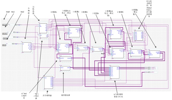
4.1設(shè)計(jì)思想本設(shè)計(jì)采用層次描述方式,采用自頂向下的方法,劃分系統(tǒng)主要模塊,畫(huà)出整體設(shè)計(jì)原理框圖。設(shè)計(jì)幾個(gè)具有各自功能的元件,然后將他們級(jí)連得到一個(gè)可預(yù)制的數(shù)字鐘。本設(shè)計(jì)具有分頻器、功能選擇器、一輸入二輸出器,計(jì)數(shù)器1至計(jì)數(shù)器6、計(jì)數(shù)器(1-3)的校正器,計(jì)數(shù)器(4-6)的校正器、防止異步清零器、異步清零器、數(shù)碼管選擇器、led燈選擇器、數(shù)碼管顯示時(shí)間器,一共16個(gè)模塊,最后把各個(gè)元件連接起來(lái)。
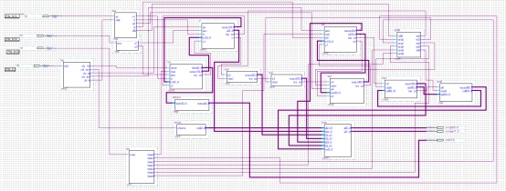
4.2設(shè)計(jì)電路圖 圖4.2.1 電路原理圖 圖4.2.2 電路總體模塊名稱圖 4.3模塊說(shuō)明
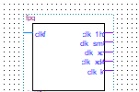
4.3.1 分頻器將50mHz的時(shí)鐘源分頻為時(shí)間計(jì)時(shí)頻率1秒、數(shù)碼管掃描頻率1毫秒、key1消抖頻率0.3秒、key2消抖頻率0.3秒、 key0消抖頻率0.3秒(如圖由上到下)。 圖4.3.1a 分頻器模塊
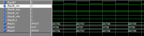
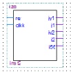
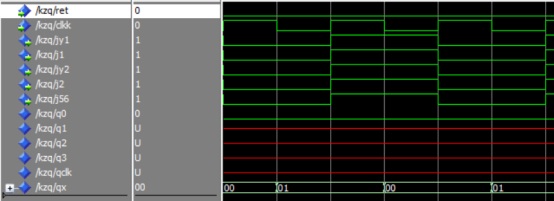
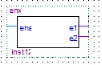
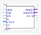
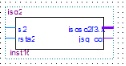
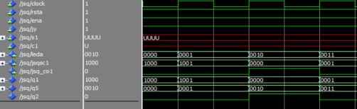
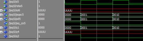
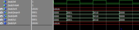
分頻器程序:如附頁(yè)。 仿真波形圖: 圖4.3.1b 4.3.2 功能選擇器:通過(guò)key0來(lái)選擇時(shí)鐘電路的功能是計(jì)時(shí)還是校正,然后輸出相應(yīng)的值給計(jì)時(shí)器1,計(jì)數(shù)器(1-3)校正器,計(jì)數(shù)器4,計(jì)數(shù)器(4-6)校正器。 圖4.3.2a 功能選擇器模塊 功能選擇器程序:如附頁(yè)。 波形仿真: 圖4.3.2b 4.3.3 一輸入二輸出器即輸入一個(gè)變量,輸出兩個(gè)和輸入值相同的變量。 圖4.3.3a 一輸入二輸出器模塊 一輸入二輸出器的程序:如附頁(yè)。 波形仿真圖: 圖4.3.3b 4.3.4 計(jì)數(shù)器1至計(jì)數(shù)器6 計(jì)數(shù)器1至計(jì)數(shù)器6都為計(jì)數(shù)的功能,前一個(gè)計(jì)數(shù)器進(jìn)位,則后一個(gè)計(jì)數(shù) 器加1,計(jì)數(shù)器1至計(jì)數(shù)器6分別對(duì)應(yīng)6個(gè)數(shù)碼管。計(jì)數(shù)器5和計(jì)數(shù)器6兩個(gè)為相互反饋?zhàn)饔茫@樣才可以為24進(jìn)制。計(jì)數(shù)器1-2為秒,60進(jìn)制;計(jì)數(shù)器3-4為分,60進(jìn)制;計(jì)數(shù)器5-6為時(shí),24進(jìn)制。 計(jì)數(shù)器1模塊 計(jì)數(shù)器2模塊 計(jì)數(shù)器3模塊 計(jì)數(shù)器4模塊 計(jì)數(shù)器5模塊 計(jì)數(shù)器6模塊 圖4.3.4a
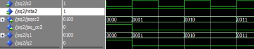
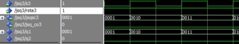
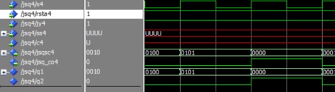
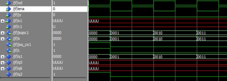
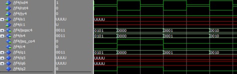
計(jì)數(shù)器1至計(jì)數(shù)器6程序:如附頁(yè)。 波形仿真圖: 計(jì)數(shù)器1 計(jì)數(shù)器2 計(jì)數(shù)器3 計(jì)數(shù)器4 計(jì)數(shù)器5 計(jì)數(shù)器6 圖4.3.4a 4.3.5 計(jì)數(shù)器(1-3)的校正器、計(jì)數(shù)器(4-6)的校正器 計(jì)數(shù)器(1-3)的校正器是對(duì)計(jì)數(shù)器1的輸出的值進(jìn)行校正或更改后,再反饋給計(jì)數(shù)器1,同時(shí)將數(shù)值輸出給后面的計(jì)數(shù)器,以達(dá)到修改計(jì)數(shù)器1到計(jì)數(shù)器3的值; 計(jì)數(shù)器(4-6)的校正器是對(duì)計(jì)數(shù)器4的輸出的值進(jìn)行校正或更改后,反饋給計(jì)數(shù)器四,同時(shí)將數(shù)值輸出給后面的計(jì)數(shù)器,以達(dá)到修改計(jì)數(shù)器4到計(jì)數(shù)器6的值。 這兩個(gè)校正器是否校正取決于功能控制器的選擇。 計(jì)數(shù)器(1-3)的校正器 計(jì)數(shù)器(4-6)的校正器 圖4.3.5a 程序代碼:如附頁(yè)。 仿真波形圖: 計(jì)數(shù)器(1-3)的校正器 計(jì)數(shù)器(4-6)的校正器 圖4.3.5b
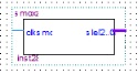
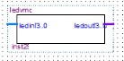
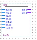
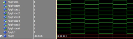
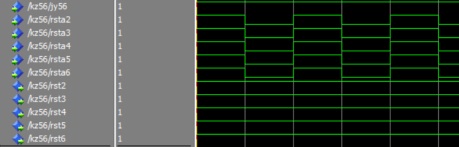
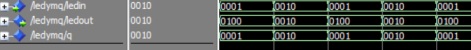
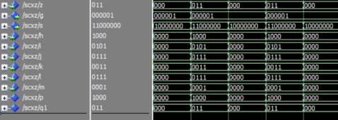
4.3.6防止異步清零器、異步清零器、數(shù)碼管選擇器、led燈選擇器、數(shù)碼管顯示時(shí)間器①異步清零器:按key2時(shí),即輸入為低電平時(shí),輸出低電平給計(jì)數(shù)器1至 計(jì)數(shù)器6的清零端,然后可以對(duì)6個(gè)計(jì)數(shù)器的數(shù)值進(jìn)行清零。 ②防止異步清零器:當(dāng)前模式為校正模式,按key2來(lái)調(diào)整計(jì)數(shù)器4至計(jì)數(shù) 器6的數(shù)值時(shí),防止計(jì)數(shù)器2至計(jì)數(shù)器6的數(shù)值被清零。 ③數(shù)碼管選擇器:用高頻率來(lái)不斷切換數(shù)碼管顯示,達(dá)到6個(gè)個(gè)數(shù)碼管動(dòng)態(tài) 顯示的程度。 ④led燈選擇器:每過(guò)一秒,在4個(gè)led燈之間切換循環(huán)顯示亮,便于觀察和檢測(cè)程序。 ⑤數(shù)碼管顯示時(shí)間器:將6個(gè)計(jì)數(shù)器的值分別用6個(gè)數(shù)碼管來(lái)顯示,數(shù)碼管掃描頻率高的話,可以達(dá)到6個(gè)數(shù)碼管一起亮的程度,即可以顯示時(shí)間。
異步清零器 防止異步清零器 數(shù)碼管選擇器 led燈選擇器 數(shù)碼管顯示時(shí)間器 圖4.3.5a 各模塊程序代碼:如附頁(yè)。 仿真波形: 異步清零器仿真波形 防止異步清零器仿真波形
數(shù)碼管選擇器波形圖 led燈選擇器波形圖 數(shù)碼管顯示時(shí)間器波形圖 圖4.3.6b 4.3.7頂層文件語(yǔ)句例化,將上述設(shè)計(jì)實(shí)體定義為元件,將這些元件與頂層的設(shè)計(jì)實(shí)體的各端口相連,實(shí)現(xiàn)自頂而下的層次化設(shè)計(jì)。
頂層文件程序:如附頁(yè)。 仿真波形圖(如圖4.3.7):分頻頻率大,不易觀察,但結(jié)果還是對(duì)的。 圖4.3.7 4.4硬件配置調(diào)試
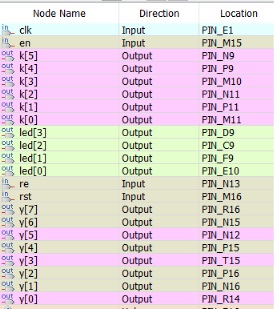
4.4.1硬件要求 (1)主芯片EP4CE6F17C8; (2)三個(gè)按鍵,按鍵key0,按鍵key1和按鍵key2; (3)ALINX開(kāi)發(fā)板。
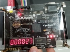
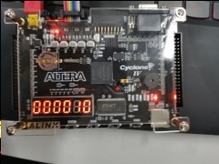
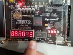
4.4.2引腳綁定圖4.4.2 4.2.3現(xiàn)象說(shuō)明將代碼燒錄進(jìn)開(kāi)發(fā)板后,按一次key0(按下后松開(kāi)),數(shù)碼管開(kāi)始計(jì)時(shí)顯示時(shí)間,時(shí)、分、秒依次為24進(jìn)制、60進(jìn)制、60進(jìn)制。此時(shí)為時(shí)間計(jì)時(shí)模式,按下key1(按下后不放)時(shí),暫停計(jì)時(shí)(如圖1);按一次key2(按下后松開(kāi)),6個(gè)數(shù)碼管清零,即時(shí)鐘的時(shí)、分、秒清零(如圖2),然后開(kāi)始計(jì)時(shí),也可以作為秒表。 再按一次key0(按下后松開(kāi)),此時(shí)模式變?yōu)樾UJ剑?strong>如圖3),通過(guò)不斷按key1(按下后松開(kāi)),來(lái)對(duì)前三個(gè)數(shù)碼管的數(shù)值進(jìn)行更改(如圖4),通過(guò)不斷按key2(按下后松開(kāi)),來(lái)對(duì)后三個(gè)數(shù)碼管的數(shù)值進(jìn)行更改(如圖5)。即key1用來(lái)更改分的個(gè)位與秒的值,key2更改分的十位與時(shí)的值。以此達(dá)到對(duì)時(shí)鐘時(shí)間的校正更改。 圖1 暫停 圖2 異步清零
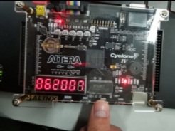
圖3 校正模式 圖4 更改右邊前三個(gè)數(shù)碼管的值 圖5 更改左邊前三個(gè)數(shù)碼管的值 5.實(shí)驗(yàn)總結(jié)5.1錯(cuò)誤和解決方法 (1)按鍵在未消抖的情況下,對(duì)電子鐘數(shù)值的校正不準(zhǔn)確不精確,按一次鍵,相當(dāng)于按過(guò)了幾百次,時(shí)鐘數(shù)值變化幅值太大了,幾百幾百的跳。 解決:對(duì)開(kāi)發(fā)板的時(shí)鐘源進(jìn)行分頻,分出一個(gè)對(duì)按鍵消抖的時(shí)鐘信號(hào),當(dāng)檢測(cè)到按下鍵了,經(jīng)過(guò)時(shí)鐘信號(hào)的上升沿時(shí),才會(huì)輸出按鍵的值,這樣就會(huì)使一個(gè)時(shí)鐘周期只會(huì)促發(fā)一次按鍵。以此來(lái)達(dá)到按鍵消抖。 (2)對(duì)計(jì)數(shù)器1進(jìn)行校正或者計(jì)數(shù)時(shí),都要出發(fā)不同的時(shí)鐘信號(hào)上升沿,但一個(gè)進(jìn)程不允許檢測(cè)多個(gè)信號(hào)的上升沿。 解決:再建立一個(gè)校正模塊(即計(jì)數(shù)器1-3的校正器),對(duì)計(jì)數(shù)器1的輸出值判斷是否要校正,若要校正,那么校正完畢后,再將數(shù)值反饋給計(jì)數(shù)器1,使計(jì)數(shù)器1的輸入值變?yōu)樾U^(guò)后的值,同時(shí)將數(shù)值輸出給下一個(gè)模塊。若無(wú)校正,則無(wú)須反饋,直接將數(shù)值輸出到下一模塊。計(jì)數(shù)器4也依此方法。以此來(lái)達(dá)到對(duì)電子鐘的時(shí)間進(jìn)行校正更改。 (3)key2有兩個(gè)功能,計(jì)時(shí)模式時(shí)為清零鍵,校正模式為對(duì)電子鐘的時(shí)間進(jìn)行更改,按下時(shí),經(jīng)常兩個(gè)功能都觸發(fā),使得每次校正后的值都被清零。 解決:建立一個(gè)模塊(防止異步清零模塊),對(duì)電子鐘此時(shí)的功能判斷,使key有不同的功能,就不會(huì)使key2的兩種功能同時(shí)觸發(fā)了。
(4)電子中的時(shí)的個(gè)位(第五個(gè)數(shù)碼管)和十位(第六個(gè)數(shù)碼管),其個(gè)位是9進(jìn)制的,十位是2進(jìn)制的,但其電子鐘的時(shí)是24進(jìn)制的。 解決:從十位(第六個(gè)數(shù)碼管)引出一個(gè)反饋給個(gè)位(第五個(gè)數(shù)碼管),當(dāng)十位為2時(shí),個(gè)位為4進(jìn)制。這樣就使得電子鐘的時(shí)為24進(jìn)制了,也不會(huì)使個(gè)位(第五個(gè)數(shù)碼管)和十位(第六個(gè)數(shù)碼管)的進(jìn)制與電子鐘的時(shí)的進(jìn)制發(fā)生沖突了。 5.2心得與體會(huì) 這次期末時(shí)間有限,使得這次設(shè)計(jì)設(shè)計(jì)電子鐘的時(shí)間太少,解決程序代碼的時(shí)間太少了,未能更進(jìn)一步對(duì)設(shè)計(jì)出來(lái)的電子鐘進(jìn)行功能的的增加,如鬧鐘,整點(diǎn)報(bào)時(shí)等功能,有點(diǎn)遺憾。但也學(xué)到了許多東西,對(duì)開(kāi)發(fā)FPGA的VHDL語(yǔ)言掌握更得更好了,解決問(wèn)題也有了一定的方法和耐心了,在設(shè)計(jì)學(xué)習(xí)的過(guò)程中更能靜下心來(lái)了。這此設(shè)計(jì)時(shí)間雖短,但對(duì)我的意義很大。我也記住了,單片機(jī)的按鍵要消抖,那么PFGA的按鍵也要消抖,無(wú)論哪種,對(duì)按鍵都要消抖。按鍵在哪都要消抖,不然對(duì)其系統(tǒng)模塊會(huì)產(chǎn)生很大的錯(cuò)誤。
附頁(yè):
代碼按目錄依次為
分頻器:
library ieee;
use ieee.std_logic_1164.all;
use ieee.std_logic_unsigned.all;
use ieee.std_logic_arith.all;
entity fpq is
port (clkf:in std_logic;
clk_1hz,clk_smg,clk_xd,clk_xd4,clk_k:out std_logic);
end fpq;
architecture fpq of fpq is
signal q1:integer range 0 to 49999999;
signal q2:integer range 0 to 49999;
signal q3:integer range 0 to 16999999;
begin
process(clkf) begin
if rising_edge(clkf) then
if q1=4999999 then q1<=0;else
q1<=q1+1;end if;
if q1>2499999 then clk_1hz<='0';else
clk_1hz<='1';
end if;
if q2=49999 then q2<=0;else
q2<=q2+1;end if;
if q2>24999 then clk_smg<='0';else
clk_smg<='1';
end if;
if q3=16999999 then q3<=0;else
q3<=q3+1;end if;
if q3>9499999 then clk_xd<='0';clk_xd4<='0';clk_k<='0';else
clk_xd<='1';clk_xd4<='1';clk_k<='1';
end if;
end if;
end process ;
end fpq;
功能選擇器:
library ieee;
use ieee.std_logic_1164.all;
use ieee.std_logic_unsigned.all;
entity kzq is
port (ret,clkk:in std_logic;
jy1,j1,jy2,j2,j56:out std_logic);
end kzq;
architecture kzq of kzq is
signal q0,q1,q2,q3,qclk:std_logic;
signal qx:std_logic_vector(1 downto 0);
begin
process(ret) begin
q0<=ret;
if q0='0' then
if falling_edge(clkk) then
if qx<1 then qx<=qx+1;else
qx<=(others=>'0');end if;end if;end if;
case qx is
when "00"=>jy1<='0';j1<='0';jy2<='0';j2<='0';j56<='0';
when "01"=>jy1<='1';j1<='1';jy2<='1';j2<='1';j56<='1';
when others=>null;
end case;
end process;
end kzq;
一輸入二輸出器:
library ieee;
use ieee.std_logic_1164.all;
use ieee.std_logic_unsigned.all;
entity enx is
port (ena:in std_logic;
e1,e2:out std_logic);
end enx;
architecture enx of enx is
begin
e1<=ena;
e2<=ena;
end enx;
計(jì)數(shù)器1:
library ieee;
use ieee.std_logic_1164.all;
use ieee.std_logic_unsigned.all;
entity jsq is
port (clock,rsta,ena,jy:in std_logic;
s1:in std_logic_vector(3 downto 0);
c1:in std_logic;
leda:out std_logic_vector(3 downto 0);
jsqsc1:out std_logic_vector(3 downto 0);
jsq_co1:out std_logic);
end jsq;
architecture jsq1 of jsq is
signal q1,q5:std_logic_vector(3 downto 0);
signal q2:std_logic;
begin
process(clock)
variable q3,q4:std_logic_vector(3 downto 0);
begin
case jy is
when '1' =>
if rsta='0' then q3:=(others=>'0');
elsif rising_edge(clock) then
if ena='0' then q1<=q1;q5<=q5; else
if q3<9 then q3:=q3+1;q2<='0';
else q3:=(others=>'0');q2<='1';end if;
if q4<3 then q4:=q4+1;
else q4:=(others=>'0');end if;end if;end if;
q1<=q3;q5<=q4;
when '0' => q1<=s1;q2<=c1;
when others =>null;
end case;
end process;
leda<=q5;jsqsc1<=q1;jsq_co1<=q2;
end jsq1;
計(jì)數(shù)器2:
library ieee;
use ieee.std_logic_1164.all;
use ieee.std_logic_unsigned.all;
entity jsq2 is
port (s2,rsta2:in std_logic;
jsqsc2:out std_logic_vector(3 downto 0);
jsq_co2:out std_logic);
end jsq2;
architecture jsq2 of jsq2 is
signal q1:std_logic_vector(3 downto 0);
signal q2:std_logic;
begin
process(s2)
variable q3:std_logic_vector(3 downto 0);
begin
if rsta2='0' then q3:=(others=>'0');q1<="0000";
elsif rising_edge(s2) then
if q3<5 then q3:=q3+1;q2<='0';
else q3:=(others=>'0');q2<='1';
end if;end if;
q1<=q3;
end process;
jsq_co2<=q2;
jsqsc2<=q1;
end jsq2;
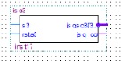
計(jì)數(shù)器3:
library ieee;
use ieee.std_logic_1164.all;
use ieee.std_logic_unsigned.all;
entity jsq3 is
port (s3,rsta3:in std_logic;
jsqsc3:out std_logic_vector(3 downto 0);
jsq_co3:out std_logic);
end jsq3;
architecture jsq3 of jsq3 is
signal q1:std_logic_vector(3 downto 0);
signal q2:std_logic;
begin
process(s3)
variable q3:std_logic_vector(3 downto 0);
begin
if rsta3='0' then q3:=(others=>'0');q1<="0000";
elsif rising_edge(s3) then
if q3<9 then q3:=q3+1;q2<='0';
else q3:=(others=>'0');q2<='1';
end if;end if;
q1<=q3;
end process;
jsq_co3<=q2;
jsqsc3<=q1;
end jsq3;
計(jì)數(shù)器4:
library ieee;
use ieee.std_logic_1164.all;
use ieee.std_logic_unsigned.all;
entity jsq4 is
port (s4,rsta4,jy4:in std_logic;
ss4:in std_logic_vector(3 downto 0);
c4:in std_logic;
jsqsc4:out std_logic_vector(3 downto 0);
jsq_co4:out std_logic);
end jsq4;
architecture jsq4 of jsq4 is
signal q1:std_logic_vector(3 downto 0);
signal q2:std_logic;
begin
process(s4,rsta4,jy4,ss4,c4)
--variable q3:std_logic_vector(3 downto 0);
begin
case jy4 is
when '1'=>
if rsta4='0' then q1<="0000";
elsif rising_edge(s4) then
if q1<5 then q1<=q1+1;q2<='0';
else q1<=(others=>'0');q2<='1';end if;end if;
--q1<=q3;
when'0'=>
q1<=ss4;q2<=c4;
when others=>null;
end case;
--q1<=q3;
end process;
jsqsc4<=q1;
jsq_co4<=q2;
end jsq4;
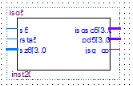
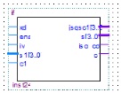
計(jì)數(shù)器5:
library ieee;
use ieee.std_logic_1164.all;
use ieee.std_logic_unsigned.all;
entity jsq5 is
port (s5,rsta5:in std_logic;
sz6:in std_logic_vector(3 downto 0);
jsqsc5:out std_logic_vector(3 downto 0);
pd5:out std_logic_vector(3 downto 0);
jsq_co5:out std_logic);
end jsq5;
architecture jsq5 of jsq5 is
signal q1,q4:std_logic_vector(3 downto 0);
signal q2:std_logic;
begin
process(s5)
variable q3:std_logic_vector(3 downto 0);
begin
q4<=sz6;
if rising_edge(s5) then
if q3<9 then q3:=q3+1;q2<='0';
else q3:=(others=>'0');q2<='1';
end if;
if ((q1=3) and (q4=2)) then q3:=(others=>'0');q2<='0';end if;end if;
if rsta5='0' then q3:=(others=>'0');q1<="0000";end if;
q1<=q3;
end process;
jsq_co5<=q2;
jsqsc5<=q1;
pd5<=q1;
end jsq5;
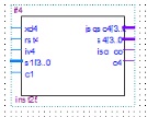
計(jì)數(shù)器6:
library ieee;
use ieee.std_logic_1164.all;
use ieee.std_logic_unsigned.all;
entity jsq6 is
port (s6,rsta6:in std_logic;
sz5:in std_logic_vector(3 downto 0);
jsqsc6:out std_logic_vector(3 downto 0);
pd6:out std_logic_vector(3 downto 0)
);
end jsq6;
architecture jsq6 of jsq6 is
signal q1,q4:std_logic_vector(3 downto 0);
begin
process(s6,sz5)
variable q3:std_logic_vector(3 downto 0);
begin
if rising_edge(s6) then
if q3<2 then q3:=q3+1;
else q3:=(others=>'0');
end if;
if ((q1=3) and (q4=2)) then q3:=(others=>'0');end if;end if;
if rsta6='0' then q3:=(others=>'0');q1<="0000";end if;
q1<=q3;
end process;
jsqsc6<=q1;
pd6<=q1;
end jsq6;
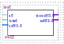
計(jì)數(shù)器(1-3)的校正器:
library ieee;
use ieee.std_logic_1164.all;
use ieee.std_logic_unsigned.all;
entity jf is
port (xd,ena,jy:in std_logic;
s1:in std_logic_vector(3 downto 0);
c1:in std_logic;
jsqsc1,s:out std_logic_vector(3 downto 0);
jsq_co1,c:out std_logic);
end jf;
architecture jf of jf is
signal q1,q5,q6:std_logic_vector(3 downto 0);
signal q2:std_logic;
begin
process(xd)
variable q3:std_logic_vector(3 downto 0);
begin
case jy is
when '0'=>
if ena='0' then
if rising_edge(xd) then
if q3<9 then q3:=q3+1;q2<='0';
else q3:=(others=>'0');q2<='1';end if;end if;end if;
q1<=q3;
when '1'=>
q1<=s1;q2<=c1;
when others =>null;
end case;
end process;
jsqsc1<=q1;jsq_co1<=q2;
s<=q1;c<=q2;
end jf;
計(jì)數(shù)器(4-6)的校正器:
library ieee;
use ieee.std_logic_1164.all;
use ieee.std_logic_unsigned.all;
entity jf4 is
port (xd4,rst4,jy4:in std_logic;
s1:in std_logic_vector(3 downto 0);
c1:in std_logic;
jsqsc4,s4:out std_logic_vector(3 downto 0);
jsq_co4,c4:out std_logic);
end jf4;
architecture jf4 of jf4 is
signal q1,q5,q6:std_logic_vector(3 downto 0);
signal q2:std_logic;
begin
process(xd4)
--variable q3:std_logic_vector(3 downto 0);
begin
case jy4 is
when '0'=>
if rst4='0' then
if rising_edge(xd4) then
if q1<5 then q1<=q1+1;q2<='0';
else q1<=(others=>'0');q2<='1';end if;end if;end if;
--q1<=q3;
when '1'=>
q1<=s1;q2<=c1;
when others =>null;
end case;
end process;
jsqsc4<=q1;jsq_co4<=q2;
s4<=q1;c4<=q2;
end jf4;
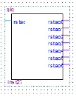
異步清零器:
library ieee;
use ieee.std_logic_1164.all;
use ieee.std_logic_unsigned.all;
entity qlq is
port (rstaq:in std_logic;
rstaq0,rstaq1,rstaq2,rstaq3,rstaq4,rstaq5,rstaq6:out std_logic);
end qlq;
architecture qlq of qlq is
signal q1:std_logic;
signal q:std_logic_vector(5 downto 0);
begin
q1<=rstaq;
rstaq0<=q1;
rstaq1<=q1;
rstaq2<=q1;
rstaq3<=q1;
rstaq4<=q1;
rstaq5<=q1;
rstaq6<=q1;
end qlq;
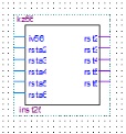
防止異步清零器:
library ieee;
use ieee.std_logic_1164.all;
use ieee.std_logic_unsigned.all;
use ieee.std_logic_arith.all;
entity kz56 is
port(jy56,rsta2,rsta3,rsta4,rsta5,rsta6:in std_logic;
rst2,rst3,rst4,rst5,rst6:out std_logic);
end kz56;
architecture kz56 of kz56 is
begin
process(jy56) begin
if jy56='0' then rst2<='1';rst3<='1';rst4<='1';rst5<='1';rst6<='1';else
rst2<=rsta2;rst3<=rsta3;rst4<=rsta4;rst5<=rsta5;rst6<=rsta6;
end if;
end process;
end kz56;
數(shù)碼管選擇器:
library ieee;
use ieee.std_logic_1164.all;
use ieee.std_logic_unsigned.all;
entity smgxz is
port (clksmg:in std_logic;
sle:out std_logic_vector(2 downto 0));
end smgxz;
architecture smgxz of smgxz is
signal q1:std_logic_vector(2 downto 0);
begin
process(clksmg)
variable asmg:std_logic_vector(2 downto 0); begin
if rising_edge(clksmg) then
if asmg<5 then asmg:=asmg+1;else
asmg:="000";
end if;end if;
q1<=asmg;
sle<=q1;
end process;
end smgxz;
led燈選擇器:
library ieee;
use ieee.std_logic_1164.all;
use ieee.std_logic_unsigned.all;
entity ledymq is
port (ledin:in std_logic_vector(3 downto 0);
ledout:out std_logic_vector(3 downto 0));
end ledymq;
architecture ledymq of ledymq is
signal q:std_logic_vector(3 downto 0);
begin
process(ledin) begin
q<=ledin;
case q is
when "0000" => ledout<="0001";
when "0001" => ledout<="0010";
when "0010" => ledout<="0100";
when "0011" => ledout<="1000";
when others=>null;
end case;
end process;
end ledymq;
數(shù)碼管顯示時(shí)間器:
library ieee;
use ieee.std_logic_1164.all;
use ieee.std_logic_unsigned.all;
entity scxz is
port( z:in std_logic_vector(2 downto 0);
g:out std_logic_vector(5 downto 0);
s:out std_logic_vector(7 downto 0);
h,i,j,k,l,m:in std_logic_vector(3 downto 0));
end scxz;
architecture scxz of scxz is
signal p:std_logic_vector(3 downto 0);
signal q1:std_logic_vector(2 downto 0);
begin
process(z,h,i,j) begin
q1<=z;
if q1="000" then p<=h; g<="111110";
elsif q1="001" then p<=i; g<="111101";
elsif q1="010" then p<=j; g<="111011";
elsif q1="011" then p<=k; g<="110111";
elsif q1="100" then p<=l; g<="101111";
elsif q1="101" then p<=m; g<="011111";
end if;
case p is
when "0000"=>s<="11000000";--0
when "0001"=>s<="11111001";--1
when "0010"=>s<="10100100";--2
when "0011"=>s<="10110000";--3
when "0100"=>s<="10011001";--4
when "0101"=>s<="10010010";--5
when "0110"=>s<="10000010";--6
when "0111"=>s<="11111000";--7
when "1000"=>s<="10000000";--8
when "1001"=>s<="10010000";--9
when others=>s<="11000000";--0
end case;
end process;
end scxz;
原理圖

制作出來(lái)的實(shí)物圖如下:

代碼下載:
 代碼與文檔.7z
(5.33 MB, 下載次數(shù): 30)
代碼與文檔.7z
(5.33 MB, 下載次數(shù): 30)
2022-4-10 21:02 上傳
點(diǎn)擊文件名下載附件
全部代碼和報(bào)告說(shuō)明
|